| You are not Logged In! |
Difference between revisions of "Public:Electrical Onboarding Fall 2023"
| (12 intermediate revisions by 4 users not shown) | |||
| Line 29: | Line 29: | ||
Please complete the setup of GitHub, KiCad, and MCUXPresso before the first onboarding meeting. If you have any questions, ask them in a Slack Public Channel. We use public channels because you are likely not the only person to have this question. If you are still stuck, you can ask us at the first meeting. | Please complete the setup of GitHub, KiCad, and MCUXPresso before the first onboarding meeting. If you have any questions, ask them in a Slack Public Channel. We use public channels because you are likely not the only person to have this question. If you are still stuck, you can ask us at the first meeting. | ||
| + | |||
| + | Remember, everything you need to know for Onboarding will be in '''public pages on the wiki!''' you don't need any other pages than the ones provided to you. | ||
==GitHub Setup== | ==GitHub Setup== | ||
| Line 35: | Line 37: | ||
Be aware that you may or may not have access to the ISC GitHub right away. We will have a form sent out in early onboarding days to get everyone access, but if you still have trouble joining later there will be a channel for questions on the Onboarding Slack. | Be aware that you may or may not have access to the ISC GitHub right away. We will have a form sent out in early onboarding days to get everyone access, but if you still have trouble joining later there will be a channel for questions on the Onboarding Slack. | ||
| − | #Go to the [[Public:GitHub|GitHub wiki page]] and ensure you have a working version of Git on your computer. | + | #Go to the [[Public:GitHub|GitHub wiki page]] and ensure you have a working version of Git on your computer. Here's the installation process for each computer: |
| − | + | ||
| − | + | === Linux === | |
| − | + | You are done, it ships with git - congrats! {{Emoji Grin}} | |
| − | + | ||
| + | === MacOS === | ||
| + | Many Macs also ship with git, you can check by running <code>git --version</code>. It will either tell you the version or how to install it. | ||
| + | |||
| + | === Windows === | ||
| + | On windows you need to install git, we recommend git bash for windows: | ||
| + | ** Download Git Bash for Windows: https://git-scm.com/downloads | ||
| + | ** Run the Installer | ||
| + | ** When ''Adjusting your PATH environment'', I recommend selecting "Use Git from Git Bash" and not using it from the Windows command prompt. | ||
| + | ** When ''Configuring Line Ending Conversion'' please use the default for your operating system unless you know what you are doing. | ||
| + | |||
| + | |||
| + | '''Important: When setting up your git folder, keep this in mind!!''' | ||
| + | *Make a Solar Car folder to copy all your Github Repos into in your main directory for organization! | ||
| + | *Copy the '''[https://github.com/IlliniSolarCar/ElecOnboarding23 ElecOnboarding23]''' Repo from Illini Solar Car's github group, ''not'' the PCB repo! The PCB repo is not public and not what we are using for this semester. | ||
| + | *Only follow the github install instructions! | ||
| + | *Look through Jarod's git [https://www.youtube.com/playlist?list=PLYWKqdG09eYIEZwwE4W5KDJekruAlOvuW youtube tutorials] to get a better understanding of why we use git as well as a few basic commands | ||
| + | *If you'd like more practice with Git, checkout these other interactive tutorials to learn more: | ||
| + | **Interactive tutorial: https://try.github.io/ | ||
| + | **Git Branching: https://learngitbranching.js.org/ | ||
This part is important to getting a good feel of our workflow. Proper push/pull form helps keep our work space clean! | This part is important to getting a good feel of our workflow. Proper push/pull form helps keep our work space clean! | ||
| Line 50: | Line 71: | ||
##Use <code>cd</code> to move to the location you want your Repository to go; it's best to use your default User directory in files; making a Solar Car folder helps keep all your solar car repositories in one place! | ##Use <code>cd</code> to move to the location you want your Repository to go; it's best to use your default User directory in files; making a Solar Car folder helps keep all your solar car repositories in one place! | ||
##Run <code>git clone <nowiki>https://github.com/IlliniSolarCar/ElecOnboarding23.git</nowiki></code> in either GitBash (Windows) or Terminal (MacOS) to clone the repository to your local machine. It should copy the code in the online repo into a local folder on your computer-- you can see it now in your file explorer! | ##Run <code>git clone <nowiki>https://github.com/IlliniSolarCar/ElecOnboarding23.git</nowiki></code> in either GitBash (Windows) or Terminal (MacOS) to clone the repository to your local machine. It should copy the code in the online repo into a local folder on your computer-- you can see it now in your file explorer! | ||
| − | + | === Library Setup === | |
| − | + | ''Note: This applies to KiCad v6 and v7 projects on GitHub since'' {{GithubPRLink|repo=isc-hw-libs|number=84}}.''This should cover most projects, and all new projects. But if you need to view older projects please update them following the instructions at [[Viewing KiCad v5 Projects]]'' | |
| − | + | ||
| − | + | Our libraries, as well as KiCad's own schematic symbol libraries, have now been moved to a submodule of the main repo. Make sure you've followed the [[Public:Github|GitHub]] directions in order to get those libraries on your machine. They are in the Libraries folder of the PCB repository. If you first open a schematic in KiCad, without setting this up, you'll probably see a lot of question marks (?) all around the schematic. To fix this follow the below instructions. | |
| − | + | ||
| − | ## | + | To setup the Libraries in General we need to let KiCad know where they are! To prevent our set-up from Interfering with your outside usage of KiCad we use ISC specific Environment Variables. |
| − | + | # Open KiCad. Start these Instructions from the home screen | |
| + | # Click on ''Preferences --> Configure Paths...'' | ||
| + | # Add a new path (press "Add") with the name <code>ISC_SYMBOL_DIR</code> and insert the path to the Libraries in your repo: <code>PathOnYourComputer\ElecOnboarding23\Hardware\Libraries</code> | ||
| + | [[File:Kicad symbol path.png|none|frame|Your Environment Variable should look like this]]This should be all you need! Our libraries are now managed using project specific libraries specified by the library tables in the project (provided with the template project) | ||
| + | |||
##*If you still have issues, follow the '''Initial Setup''' instructions [[Public:GitHub/PCB|here]]. (The page is setup for using the PCB repository. Don't use that! We are using the new Onboarding repo this year for an easier work space. Please follow all the instructions but use the [https://github.com/IlliniSolarCar/ElecOnboarding23.git Onboarding] repository instead.) | ##*If you still have issues, follow the '''Initial Setup''' instructions [[Public:GitHub/PCB|here]]. (The page is setup for using the PCB repository. Don't use that! We are using the new Onboarding repo this year for an easier work space. Please follow all the instructions but use the [https://github.com/IlliniSolarCar/ElecOnboarding23.git Onboarding] repository instead.) | ||
#Setup KiCad by following the [[Public:KiCad|KiCad]] '''First Time Setup''' instructions. | #Setup KiCad by following the [[Public:KiCad|KiCad]] '''First Time Setup''' instructions. | ||
| Line 102: | Line 127: | ||
On top of that, you may have to work on these projects '''outside''' of team meetings! This is standard within solar car; not all of our work is done during the two times a week that we meet. Don't worry if it takes you extra time to work on these projects. | On top of that, you may have to work on these projects '''outside''' of team meetings! This is standard within solar car; not all of our work is done during the two times a week that we meet. Don't worry if it takes you extra time to work on these projects. | ||
| + | ==Hardware== | ||
| + | Hardware is much more tedious than firmware. When it comes to schematic design and layout, datasheets are a critical part of the project, which is why we use PartsBox to organize our part inventory and store all relevant information. These projects will get you used to the KiCad software as well as our typical process of researching datasheets, creating BOMs, generating DFMs, etc. These are all integral parts of the solar car PCB design flow! | ||
| + | |||
| + | ===Project 1: LED Circuit=== | ||
| + | This project is relatively simple: in order to get used to the KiCad application and a few of its typical shortcuts, you'll build an LED circuit in the schematic editor before laying it out. Ryder has made a few videos on youtube to walk through the process, but here are the steps written out: | ||
| + | |||
| + | *Make sure you have KiCad v7 downloaded. You'll have a hard time opening any files if you don't. | ||
| + | *In your File Explorer, you'll want to navigate to the folder you copied the Onboarding Repo into (make sure that you copied the ElecOnboarding23 Repo when setting up Git rather than the B-fw or PCB repos). | ||
| + | *In the Hardware folder, you should see a Dev folder. Navigate into that and then go into the Template_v0.0 folder. There is another folder named Lights_Onboarding_v0_1 that has a developed project inside that you can take a look at, but for right now you won't be needing it. | ||
| + | *Select everything in the folder and copy/paste to a new folder in the Hardware directory (two folders back); you can name the folder something like "prog1" to differentiate that it is your first hardware project! | ||
| + | *Now you have a couple of files in your folder. These should be the seven files you see: | ||
| + | *#fb-lib-table (your footprint libraries table, this is crucial to making your layouts exist and print properly!!) | ||
| + | *#sym-lib-table (your symbol libraries table, this is important to making your schematics exist!) | ||
| + | *#template_v0.0_specs.md | ||
| + | *#Template_v0.0_v7.kicad_pcb | ||
| + | *#Template_v0.0_v7.kicad_pro | ||
| + | *#Template_v0.0_v7.kicad_sch | ||
| + | *#Title_Block.kicad_wks | ||
| + | *These files are important to making any board project in KiCad! Please always make sure that at least these 7 files are included in any project. | ||
| + | *You will need to change any file that starts with "Template_v0.0_v7" to the name of your project. I recommend that it matches your folder name-- so in this case, your KiCad project file name should look like "prog1.kicad_pcb". Keep the kicad_pcb at the end!! | ||
| + | *Double click the file that ends in "kicad_pro" to open the KiCad Project. Your screen should look like this![[File:KiCad Interface.png|center|alt=|frameless]] | ||
| + | *This is the project manager for all KiCad projects. It has navigation to each of the tools you need to build a board. | ||
| + | *#The Schematic Editor allows you to work on schematics, which is where you can choose circuit components and design your circuits. | ||
| + | *#The PCB Editor uses the information you put in the Schematic Editor to produce a footprint puzzle that you'll put together to create the physical dimensions of the board. | ||
| + | *#The other tools are less important. For this project and a majority of Solar Car projects, you won't really need to use them. | ||
| + | *Here's an in-depth [https://www.youtube.com/watch?v=aVUqaB0IMh4&ab_channel=Phil%E2%80%99sLab KiCad tutorial] that explains the different Editors and each of the tools you can use for your boards. There are a multitude of shortcuts and tricks you'll learn to use the more you use KiCad, that can make board design quicker and easier! | ||
| + | *'''To start the project,''' you want to open the Schematic Editor first. | ||
| + | *You'll see that the sheet that opens up is empty. This is where you will design your project! The first thing you can do is to double-click on the title block in the bottom left corner and update the comments and date on the schematic sheet. You can see what this looks like below:[[File:Title Editing in KiCad.jpg|center|alt=|frameless]] | ||
| + | *Now you can start working on the circuit! From here on out you can use tricks you've learned on the previous video linked above (or watch through [https://www.youtube.com/watch?v=6VV7DvNGEA8&list=PLYWKqdG09eYLCqh8V8gjJpYXOJ60yJ5xG&index=3&ab_channel=IlliniSolarCarTeam Rahul's KiCad tutorial] from a few years ago) to follow the below instructions. The specs.md file in your folder also has the requirements for this project if you don't want to keep checking back to this page. | ||
| + | *'''To build the circuit for this project:''' | ||
| + | **Follow [https://www.youtube.com/watch?v=6VV7DvNGEA8&list=PLYWKqdG09eYLCqh8V8gjJpYXOJ60yJ5xG&index=3&ab_channel=IlliniSolarCarTeam Rahul's KiCad tutorial] steps. This will teach you important knowledge on building circuits, what tools we normally use, and how to import your schematics from one editor to another. Be sure to watch through the videos to have a good understanding of what our interface looks like! Some of what Rahul explains in his videos is already written out here. You can start watching from his second video to go straight to the onboarding project! | ||
| + | **There are a few differences from Rahul's video to our onboarding. ''Please be aware of a few things while you watch this tutorial!'' | ||
| + | **#The version of KiCad we use is v7. Rahul uses v5, but that was a couple of years ago! Make sure you're aware of the version you're using since some library errors can occur between different versions. | ||
| + | **#Use the onboarding repo for your work only. | ||
| + | **#When adding power flags to your circuit in the first Schematic video, you will need to add ''two more'' components: one PWR_FLAG on both your +3v3 and GND wires. It should look like this:[[File:PWR FLAGS.png|center|frameless]] | ||
| + | **#''In the layout tutorial,'' when you add dimensions to your board, you'll need to go to the top bar and select ''[Place -> Add Orthogonal Dimension],'' seen below:[[File:Add Orthogonal Dimension.png|center|frameless]] | ||
| + | **#Remember that your version of KiCad will look different from Rahul's! Things change with time, as did the software. Don't panic! Everything he can do in the video, you can too. Try playing around with the tools for a while before asking one of the elec members if you're having issues with the software. | ||
| + | |||
| + | *After watching through Rahul's fourth tutorial, you're done with the schematic and layout! Normally you'll need to export your Bill of Materials (A.K.A BOM) to a spreadsheet and generate a DFM, but we'll learn these later during the harder hardware project. These are two important steps to our process that you can learn from the wiki later since it's not a huge focus during onboarding. | ||
| + | *All done! You've just made your first board. Congrats! Now push your changes in your branch to the online repo using <code>''git add -u''</code> to add any updates you made to the files you worked on, then <code>''git'' ''commit -m "[some comment here]"''</code> to commit, and finally ''<code>git push</code>'' to push your changes to the onboarding repo. | ||
| + | |||
| + | ===(Hard) Project 2: Horns Board=== | ||
| + | Note, this is a long project. Do not try and finish this in one night, pace yourself. | ||
| + | |||
| + | So you've finished both easy projects and decided to start the harder hardware project! This hardware project #2 is a more in-depth look into how we do actual schematic and board design, using one of our old boards we designed for use in our solar cars! | ||
| + | |||
| + | We will be having you design a board that we really use on the car. This is the Horn Breakout board which we use to power the electronic horn. It will get +24V from the Low Voltage Bus Board and a digital signal from the Dash Board to sound a very loud horn. You will be going through the whole process, from Specs to Schematic to Layout. Feel free to work as a group and do not be discouraged if this is difficult! | ||
| + | |||
| + | Since you already know how to use KiCad, there's no setup needed aside from making a new folder in the Hardware directory of your local repo and naming it something like "jdoe_Horns_v1.0." | ||
| + | |||
| + | '''Here are the instructions for the second hardware project!''' | ||
| + | |||
| + | * Copy/paste the template files into your second project folder and rename everything starting with "Template..." to your second project name again. | ||
| + | |||
| + | Using a text editor, edit the specs file to be updated for everything needed for the horns board | ||
| + | |||
| + | * We will have 2 of these horns in series, so it would be nice to add the link to the specs | ||
| + | * We will have 2 main High-Level Requirements | ||
| + | ** A Horn On/Off which will be a digital signal for whether or not it should be on | ||
| + | ** A Horn Output which will output 24V at 150 mAmps | ||
| + | * As far as communication protocols, we use a digital GPIO to switch the horn | ||
| + | * We will have 4 connectors for the board | ||
| + | ** Power in | ||
| + | ** Horn Control | ||
| + | ** And then 2 Horn outs linked in series | ||
| + | * There are will be no ICs | ||
| + | * You can choose to add a Button that would be used to debug the board | ||
| + | * The power system is 24V from the LV Bus | ||
| + | * You should add test points to any net you would like to add | ||
| + | * You can add LED Indicators to any net you would like | ||
| + | |||
| + | Once you write the Spec Sheet, push it to your branch and move onto the Schematic | ||
| + | |||
| + | * The first thing to set up for the schematic is the connectors | ||
| + | ** You will need a 1x3pin connector for power, we use 3 pin connectors for Power so that they do not get plugged in backwards. We put +24V in the middle and two GND pins on the outside | ||
| + | ** You will want a 1x2pin connector for Horn Control. We want 1 pin to be grounded and another to be connected to a "Net Label" (Click L to add one). Give it a meaningful name | ||
| + | ** You will want two 1x2pin connectors for Horn Out. You need to link them together in series, from HORN_IN to 24V. | ||
| + | * You will next want to add a way of switching from "on to off." To perform a switch at this level, we use a Mosfet. We recommend using the IRFR010PBF (this is the MPN), but you can go to octopart.com to find replacements. | ||
| + | ** Source should be tied GND, Drain should be tied to the HORN_IN of the series connectors, and Gate should be tied to the horn control net label you created earlier. | ||
| + | ** You will want a 1k ohm resistor and a .1uF capacitor between HORN_CTL and GND before it reaches the mosfet to help with noise reduction. | ||
| + | ** Between the mosfet and the connectors, add a 2A fuse. | ||
| + | * The next thing to add are capacitors between +24V and GND | ||
| + | ** We recommend adding 3 .1uF capacitors, 2 1uF capacitors, 2 10uF capacitors, and 1 100uF polarized radial capacitor in parallel | ||
| + | * Finally, you will want to add a rectifier diode from HORN_IN to +24V to ensure we do not short power to ground. You can use ES2DA-13-F or find an alternative from octopart.com. | ||
| + | |||
| + | After you have finished your schematic, make sure to run ERC. Once you pass, push your schematic to github and move onto the layout. Once all parts are added to the layout, and you pass DRC, push to your branch again. Once pushed, add a blurb to your pull request saying what you have done. | ||
| + | |||
| + | |||
| + | The final step in the process is to complete an Instant DFM Report . The first thing you will need to do is get the Gerber files for your PCB. In your layout editor, go File > Fabrication Outputs > Gerbers. Follow [http://support.seeedstudio.com/knowledgebase/articles/1824574-how-to-generate-gerber-and-drill-files-from-kicad this tutorial] for instructions on how to extract the files. Once you have gotten the files, compress them into a zip file, push the zip file (not each individual gerber) to github, and use [https://instantdfm.bayareacircuits.com/ Bay Area Circuits' Instant DFM] to check if your board matches their manufacturing capabilities. Once all of them are green, add a link to the pdf file to your pull request, and you are done with your project! | ||
==Firmware== | ==Firmware== | ||
===Project 1: Heartbeat === | ===Project 1: Heartbeat === | ||
| − | If you're not familiar with or you'd like to brush up on C++ / object-oriented programming, please read through the [[Onboarding Fall 2022 - Basics of C++|basics of C++ (with firmware examples)]] before starting this project. | + | If you're not familiar with or you'd like to brush up on C++ / object-oriented programming, please read through the [[Public:Onboarding Fall 2022 - Basics of C++|basics of C++ (with firmware examples)]] before starting this project. |
| − | Please read through the [[Onboarding 2021 - What is Firmware?|simplified explanation of firmware]] as well as the [[General:Firmware|slightly more detailed explanation]]. Reading through the [[Firmware Standards|general firmware standards]] is optional for this project but good if you'd like to do more firmware later. | + | Please read through the [[Public:Onboarding 2021 - What is Firmware?|simplified explanation of firmware]] as well as the [[General:Firmware|slightly more detailed explanation]]. Reading through the [[Public:Firmware Standards|general firmware standards]] is optional for this project but good if you'd like to do more firmware later. |
====What You'll Be Doing==== | ====What You'll Be Doing==== | ||
| Line 114: | Line 228: | ||
=====Getting Started===== | =====Getting Started===== | ||
| − | Make sure that you’ve [[MCUXpresso|set up MCUXpresso]] on your computer. This is an IDE, similar to Visual Studio, Eclipse, or IntelliJ, except that it provides more support for microcontroller programming. Follow the steps for your operating system carefully or you could encounter problems later. | + | Make sure that you’ve [[Public:MCUXpresso|set up MCUXpresso]] on your computer. This is an IDE, similar to Visual Studio, Eclipse, or IntelliJ, except that it provides more support for microcontroller programming. Follow the steps for your operating system carefully or you could encounter problems later. |
Make sure that you’ve cloned the Onboarding repository on your computer. This branch has the starter code for this project, in the <code>project_1</code> folder. | Make sure that you’ve cloned the Onboarding repository on your computer. This branch has the starter code for this project, in the <code>project_1</code> folder. | ||
| Line 179: | Line 293: | ||
'''There's an alternate way you can blink the LED - look at the <code>timing.addCallback(...)</code>method in the main.cpp <code>setup()</code> function for a clue. You can try to figure out how to blink the LED this way if you'd like.''' | '''There's an alternate way you can blink the LED - look at the <code>timing.addCallback(...)</code>method in the main.cpp <code>setup()</code> function for a clue. You can try to figure out how to blink the LED this way if you'd like.''' | ||
| − | == | + | === Project 2: Potentiometer Blink Rate === |
| − | + | In Project 2, you will be adding to the code that you wrote in Project 1. This new code should use adjust the blinking rate of the LED using a potentiometer as input. | |
| − | + | '''What You Need To Do''' | |
| − | |||
| − | + | Once again, you will be instantiating a pin object. However, instead of a DigitalOut object, you will be instantiating an input pin object for a potentiometer (hint: pay attention to the comments!). If you're not familiar with a potentiometer, it is a variable resistor. As you turn the knob on the potentiometer to reduce resistance across a path, the voltage across that path will increase (following Ohm's Law). We can read this voltage and use it to carry out a task in firmware. You will be able to find more information about the object that you should be instantiating in <code>mbed</code>. Be careful about what value is being returned by the function you are using to read your input! Once finished with that, you will write code in the <code>while (!shutdown) {...}</code> loop in '''main.cpp''' that uses the potentiometer object to modify the task rate that you used in Project 1. | |
| − | |||
| − | |||
| − | |||
| − | |||
| − | |||
| − | |||
| − | |||
| − | |||
| − | |||
| − | |||
| − | |||
| − | |||
| − | |||
| − | |||
| − | |||
| − | |||
| − | |||
| − | |||
| − | |||
| − | |||
| − | |||
| − | |||
| − | |||
| − | |||
| − | |||
| − | |||
| − | |||
| − | |||
| − | |||
| − | |||
| − | |||
| − | |||
| − | |||
| − | |||
| − | |||
Latest revision as of 10:42, 19 September 2023
Welcome to Illini Solar Car! We are glad you’re here!
Illini Solar Car is one of the largest engineering projects on campus. Our work is incredibly multifaceted (there are even times when you’ll be working on two cars simultaneously), diverse in majors and members, expensive (we go through 6 figures of resources per year), and rewarding. You can think of all the expenses as an investment in you as they provide you with unmatched real-world and hands-on experience which can be invaluable when looking for jobs or when you eventually get to doing it later in school.
Due to the scope of this project, the team does have a somewhat large learning curve. In order to help with this learning curve we introduced this wiki in Spring 2018 to put what institutional knowledge we have in an accessible location as opposed to only being in peoples heads. Older members will certainly help you to learn (especially with hands-on and technical skills) but we also expect you to be able to pick up on background from the wiki and be proactive about learning about the team. Perusing this wiki should help you do so. It will also help you become familiar with the team and how we operate. The contents of this page should serve as an overview of the Fall 2023 onboarding process and some useful getting started info.
You will notice that even though there are already 5 years' worth of information on this site, there are always new pages being added and updated. As you are learning things please feel free to contribute! Additionally, if there is valuable info you feel is missing please add it to the ((Wanted Content|Wanted Pages)) list.
This page is created to integrate all the electrical onboarding links onto a single page and help provide a hub for the onboarding process. In general, there will be 4 methods of accessing all the electrical team's information for onboarding:
- Slack (Please check regularly)
- GitHub
- Google Drive
- Wiki (You're already here!)
Each of these sites host information on events and meetings, or important files from testing, building past cars, etc. Please check these to stay updated and learn more about the team!
Planned Dates/ Deadlines
Most of Fall 23 Onboarding will be done in-person at onboarding meetings, so new members will have the chance to receive guidance from older team members if they need extra help during the process. However, a majority of onboarding can be done by following the guidelines and tutorials set up later on in this page. Below is a general outline of when and where meetings will be. Make sure to show up to these and other new member events to get to know your seniors and get comfortable with your team!
Meeting Days & Times: Mondays & Wednesdays @ 7:00 PM
Location: 1015 ECE Building (306 N Wright St)
Onboarding weeks: 4th September - 2nd October
During this time you will be doing three projects that will teach you important knowledge and skills to have on the electrical team. They'll be split up with one week each to the first two projects, and the last two weeks will be spent doing a harder project of your choice. Each of these projects will be detailed here, with links to relevant pages that you will need to properly do the work. To begin, you'll need to set up a few accounts and download some apps. See below.
Please complete the setup of GitHub, KiCad, and MCUXPresso before the first onboarding meeting. If you have any questions, ask them in a Slack Public Channel. We use public channels because you are likely not the only person to have this question. If you are still stuck, you can ask us at the first meeting.
Remember, everything you need to know for Onboarding will be in public pages on the wiki! you don't need any other pages than the ones provided to you.
GitHub Setup
GitHub is a tool we use to share all of our work as a team. It is a great way to ensure all the current work stays updated and there are very little conflicts when working together. Most industry professionals use GitHub for code, however we also use it with our KiCad projects as well as code. You may be familiar with the GitHub site, but not so much with our use of Git Bash, so there are a few resources here to help you get familiar. Git is hard to learn so don't be upset if you don't understand how it works at the end of onboarding, you'll get more practice and become a pro later :)
Be aware that you may or may not have access to the ISC GitHub right away. We will have a form sent out in early onboarding days to get everyone access, but if you still have trouble joining later there will be a channel for questions on the Onboarding Slack.
- Go to the GitHub wiki page and ensure you have a working version of Git on your computer. Here's the installation process for each computer:
Linux
You are done, it ships with git - congrats! 😀
MacOS
Many Macs also ship with git, you can check by running git --version. It will either tell you the version or how to install it.
Windows
On windows you need to install git, we recommend git bash for windows:
- Download Git Bash for Windows: https://git-scm.com/downloads
- Run the Installer
- When Adjusting your PATH environment, I recommend selecting "Use Git from Git Bash" and not using it from the Windows command prompt.
- When Configuring Line Ending Conversion please use the default for your operating system unless you know what you are doing.
Important: When setting up your git folder, keep this in mind!!
- Make a Solar Car folder to copy all your Github Repos into in your main directory for organization!
- Copy the ElecOnboarding23 Repo from Illini Solar Car's github group, not the PCB repo! The PCB repo is not public and not what we are using for this semester.
- Only follow the github install instructions!
- Look through Jarod's git youtube tutorials to get a better understanding of why we use git as well as a few basic commands
- If you'd like more practice with Git, checkout these other interactive tutorials to learn more:
- Interactive tutorial: https://try.github.io/
- Git Branching: https://learngitbranching.js.org/
This part is important to getting a good feel of our workflow. Proper push/pull form helps keep our work space clean!
KiCad Setup
KiCad is an electrical CADing software that our team uses to design the custom printed circuit boards (aka PCBs) for the solar car. All of our designs exist on the Illini Solar Car GitHub page in the PCB repository. You will clone this repository later and any hardware contribution you make to the team will be in here forever :)
- First download KiCad onto your computer from here, use the most recent stable version available.
- Next, clone the Onboarding repository.
- Use
cdto move to the location you want your Repository to go; it's best to use your default User directory in files; making a Solar Car folder helps keep all your solar car repositories in one place! - Run
git clone https://github.com/IlliniSolarCar/ElecOnboarding23.gitin either GitBash (Windows) or Terminal (MacOS) to clone the repository to your local machine. It should copy the code in the online repo into a local folder on your computer-- you can see it now in your file explorer!
- Use
Library Setup
Note: This applies to KiCad v6 and v7 projects on GitHub since ![]() isc-hw-libs#84.This should cover most projects, and all new projects. But if you need to view older projects please update them following the instructions at Viewing KiCad v5 Projects
isc-hw-libs#84.This should cover most projects, and all new projects. But if you need to view older projects please update them following the instructions at Viewing KiCad v5 Projects
Our libraries, as well as KiCad's own schematic symbol libraries, have now been moved to a submodule of the main repo. Make sure you've followed the GitHub directions in order to get those libraries on your machine. They are in the Libraries folder of the PCB repository. If you first open a schematic in KiCad, without setting this up, you'll probably see a lot of question marks (?) all around the schematic. To fix this follow the below instructions.
To setup the Libraries in General we need to let KiCad know where they are! To prevent our set-up from Interfering with your outside usage of KiCad we use ISC specific Environment Variables.
- Open KiCad. Start these Instructions from the home screen
- Click on Preferences --> Configure Paths...
- Add a new path (press "Add") with the name
ISC_SYMBOL_DIRand insert the path to the Libraries in your repo:PathOnYourComputer\ElecOnboarding23\Hardware\Libraries

This should be all you need! Our libraries are now managed using project specific libraries specified by the library tables in the project (provided with the template project)
- If you still have issues, follow the Initial Setup instructions here. (The page is setup for using the PCB repository. Don't use that! We are using the new Onboarding repo this year for an easier work space. Please follow all the instructions but use the Onboarding repository instead.)
- Setup KiCad by following the KiCad First Time Setup instructions.
- Note: We use KiCad v7. If there are any files in the future that are in previous versions, just save them as v7. Anything v5 and below will have a libraries issue that can be resolved by copy/pasting the lib files from a v7 project into that folder.
After Completing Setup
- Create a Branch in the Onboarding Repository, this branch will be exclusive to you.
- Run
git checkout -b jdoe2_onboarding(replace jdoe2 with your netid [your illinois email without the @illinois.edu]) to create the branch - Run
git statusto ensure you are on the correct branch - Run
git push --set-upstream origin jdoe2_onboardingto push your new branch to the remote repository
- Run
- Start working on the Onboarding Projects! We created a series of projects to act as goals to progress yourselves with KiCad. We have 1 required project and one harder one for you to choose from as your third project. You are required to complete at least one advanced project, either hardware or firmware. We'll be there to help you, so don't worry about the projects being too hard, just do your best!
- While working on the onboarding projects take a look at these useful guidelines.
- KiCad Schematic Conventions - has information about specifics regarding each part of the schematic design from naming conventions to symbol creation to part selection
- KiCad Layout Standards - has information about the design guidelines for PCBs and illustrates what is allowed and what isn't
- After Completing the schematic for your first onboarding project push your work to the Onboarding repository using your git knowledge
- Don't worry that you're not done yet, pushing is for us to see that you're making progress!
- Finish the layout and push the changes to your branch to get more feedback. Our senior members will be reviewing and approving everything you push, so keep an eye on your branch for any comments your leads may have.
- You're done! Use all this knowledge for any of the hardware projects you do in the future.
MCUXPresso Setup
In order to control our various hardware components, we write firmware code to allow various processes to happen. For example if the brake is pressed, we have a hall effect-sensor that gets triggered which sends an enable signal to our Dash in order to turn on the brake lights. All of our firmware is written in C++ and we use MCUXpresso, an eclipse based IDE.
- Go through the MCUXpresso setup instructions. Don't worry about setting up PCB, ARGO-fw, B-fw (or any of the FW repos) as we are using the Onboarding repository for everything.
- B-fw is the old firmware repo for Brizo. We won't be using it for the onboarding process nor for our third car, but it's good to have in case we are still testing on Brizo by the time Onboarding finishes!
- All of the coding that you do for Onboarding will be pushed to the Onboarding repo. Don't worry about pushing to the others for now.
- Make sure to double click on
update_LibraryProjectFiles.shto get the projects to work in MCUXpresso.
- Follow the Building and Debugging Code instructions to ensure you are able to setup the project files and build the skeleton code. For the Flashing/Debugging Section: we'll work on getting that situated as you get your firmware project closer to being completed.
- Most likely, you will learn this through watching members and looking it up on your own for another project down the line. Don't be afraid to ask for help!
After Completing Setup
- As stated above, we have a few firmware projects on this page for you to do. One will be a required firmware project that's easier, and the other will be an optional advanced project to choose from between hardware and firmware.
- Here are some links to get you more familiar with firmware:
- Firmware Standards
- Basics of C++
- Basics of Communications Protocols
Onboarding Projects
Below will be the projects for each of the hardware and firmware groups.
You are required to finish the easy projects for both firmware and hardware in the first two weeks of onboarding before choosing one harder project from either firmware or hardware to complete in the last two weeks of onboarding. This is the criteria to complete your technical introduction to ISC and you will not be able to join the club if you do not finish!
Team leadership and senior members will be happy to help and answer questions, so be sure to use the onboarding meetings as time to discuss any issues you have in person.
On top of that, you may have to work on these projects outside of team meetings! This is standard within solar car; not all of our work is done during the two times a week that we meet. Don't worry if it takes you extra time to work on these projects.
Hardware
Hardware is much more tedious than firmware. When it comes to schematic design and layout, datasheets are a critical part of the project, which is why we use PartsBox to organize our part inventory and store all relevant information. These projects will get you used to the KiCad software as well as our typical process of researching datasheets, creating BOMs, generating DFMs, etc. These are all integral parts of the solar car PCB design flow!
Project 1: LED Circuit
This project is relatively simple: in order to get used to the KiCad application and a few of its typical shortcuts, you'll build an LED circuit in the schematic editor before laying it out. Ryder has made a few videos on youtube to walk through the process, but here are the steps written out:
- Make sure you have KiCad v7 downloaded. You'll have a hard time opening any files if you don't.
- In your File Explorer, you'll want to navigate to the folder you copied the Onboarding Repo into (make sure that you copied the ElecOnboarding23 Repo when setting up Git rather than the B-fw or PCB repos).
- In the Hardware folder, you should see a Dev folder. Navigate into that and then go into the Template_v0.0 folder. There is another folder named Lights_Onboarding_v0_1 that has a developed project inside that you can take a look at, but for right now you won't be needing it.
- Select everything in the folder and copy/paste to a new folder in the Hardware directory (two folders back); you can name the folder something like "prog1" to differentiate that it is your first hardware project!
- Now you have a couple of files in your folder. These should be the seven files you see:
- fb-lib-table (your footprint libraries table, this is crucial to making your layouts exist and print properly!!)
- sym-lib-table (your symbol libraries table, this is important to making your schematics exist!)
- template_v0.0_specs.md
- Template_v0.0_v7.kicad_pcb
- Template_v0.0_v7.kicad_pro
- Template_v0.0_v7.kicad_sch
- Title_Block.kicad_wks
- These files are important to making any board project in KiCad! Please always make sure that at least these 7 files are included in any project.
- You will need to change any file that starts with "Template_v0.0_v7" to the name of your project. I recommend that it matches your folder name-- so in this case, your KiCad project file name should look like "prog1.kicad_pcb". Keep the kicad_pcb at the end!!
- Double click the file that ends in "kicad_pro" to open the KiCad Project. Your screen should look like this!
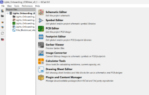
- This is the project manager for all KiCad projects. It has navigation to each of the tools you need to build a board.
- The Schematic Editor allows you to work on schematics, which is where you can choose circuit components and design your circuits.
- The PCB Editor uses the information you put in the Schematic Editor to produce a footprint puzzle that you'll put together to create the physical dimensions of the board.
- The other tools are less important. For this project and a majority of Solar Car projects, you won't really need to use them.
- Here's an in-depth KiCad tutorial that explains the different Editors and each of the tools you can use for your boards. There are a multitude of shortcuts and tricks you'll learn to use the more you use KiCad, that can make board design quicker and easier!
- To start the project, you want to open the Schematic Editor first.
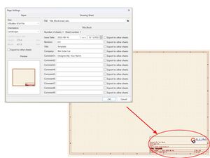
- You'll see that the sheet that opens up is empty. This is where you will design your project! The first thing you can do is to double-click on the title block in the bottom left corner and update the comments and date on the schematic sheet. You can see what this looks like below:
- Now you can start working on the circuit! From here on out you can use tricks you've learned on the previous video linked above (or watch through Rahul's KiCad tutorial from a few years ago) to follow the below instructions. The specs.md file in your folder also has the requirements for this project if you don't want to keep checking back to this page.
- To build the circuit for this project:
- Follow Rahul's KiCad tutorial steps. This will teach you important knowledge on building circuits, what tools we normally use, and how to import your schematics from one editor to another. Be sure to watch through the videos to have a good understanding of what our interface looks like! Some of what Rahul explains in his videos is already written out here. You can start watching from his second video to go straight to the onboarding project!
- There are a few differences from Rahul's video to our onboarding. Please be aware of a few things while you watch this tutorial!
- The version of KiCad we use is v7. Rahul uses v5, but that was a couple of years ago! Make sure you're aware of the version you're using since some library errors can occur between different versions.
- Use the onboarding repo for your work only.
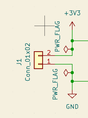
- When adding power flags to your circuit in the first Schematic video, you will need to add two more components: one PWR_FLAG on both your +3v3 and GND wires. It should look like this:
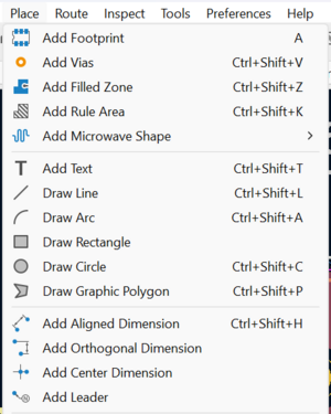
- In the layout tutorial, when you add dimensions to your board, you'll need to go to the top bar and select [Place -> Add Orthogonal Dimension], seen below:
- Remember that your version of KiCad will look different from Rahul's! Things change with time, as did the software. Don't panic! Everything he can do in the video, you can too. Try playing around with the tools for a while before asking one of the elec members if you're having issues with the software.


- After watching through Rahul's fourth tutorial, you're done with the schematic and layout! Normally you'll need to export your Bill of Materials (A.K.A BOM) to a spreadsheet and generate a DFM, but we'll learn these later during the harder hardware project. These are two important steps to our process that you can learn from the wiki later since it's not a huge focus during onboarding.
- All done! You've just made your first board. Congrats! Now push your changes in your branch to the online repo using
git add -uto add any updates you made to the files you worked on, thengit commit -m "[some comment here]"to commit, and finallygit pushto push your changes to the onboarding repo.
(Hard) Project 2: Horns Board
Note, this is a long project. Do not try and finish this in one night, pace yourself.
So you've finished both easy projects and decided to start the harder hardware project! This hardware project #2 is a more in-depth look into how we do actual schematic and board design, using one of our old boards we designed for use in our solar cars!
We will be having you design a board that we really use on the car. This is the Horn Breakout board which we use to power the electronic horn. It will get +24V from the Low Voltage Bus Board and a digital signal from the Dash Board to sound a very loud horn. You will be going through the whole process, from Specs to Schematic to Layout. Feel free to work as a group and do not be discouraged if this is difficult!
Since you already know how to use KiCad, there's no setup needed aside from making a new folder in the Hardware directory of your local repo and naming it something like "jdoe_Horns_v1.0."
Here are the instructions for the second hardware project!
- Copy/paste the template files into your second project folder and rename everything starting with "Template..." to your second project name again.
Using a text editor, edit the specs file to be updated for everything needed for the horns board
- We will have 2 of these horns in series, so it would be nice to add the link to the specs
- We will have 2 main High-Level Requirements
- A Horn On/Off which will be a digital signal for whether or not it should be on
- A Horn Output which will output 24V at 150 mAmps
- As far as communication protocols, we use a digital GPIO to switch the horn
- We will have 4 connectors for the board
- Power in
- Horn Control
- And then 2 Horn outs linked in series
- There are will be no ICs
- You can choose to add a Button that would be used to debug the board
- The power system is 24V from the LV Bus
- You should add test points to any net you would like to add
- You can add LED Indicators to any net you would like
Once you write the Spec Sheet, push it to your branch and move onto the Schematic
- The first thing to set up for the schematic is the connectors
- You will need a 1x3pin connector for power, we use 3 pin connectors for Power so that they do not get plugged in backwards. We put +24V in the middle and two GND pins on the outside
- You will want a 1x2pin connector for Horn Control. We want 1 pin to be grounded and another to be connected to a "Net Label" (Click L to add one). Give it a meaningful name
- You will want two 1x2pin connectors for Horn Out. You need to link them together in series, from HORN_IN to 24V.
- You will next want to add a way of switching from "on to off." To perform a switch at this level, we use a Mosfet. We recommend using the IRFR010PBF (this is the MPN), but you can go to octopart.com to find replacements.
- Source should be tied GND, Drain should be tied to the HORN_IN of the series connectors, and Gate should be tied to the horn control net label you created earlier.
- You will want a 1k ohm resistor and a .1uF capacitor between HORN_CTL and GND before it reaches the mosfet to help with noise reduction.
- Between the mosfet and the connectors, add a 2A fuse.
- The next thing to add are capacitors between +24V and GND
- We recommend adding 3 .1uF capacitors, 2 1uF capacitors, 2 10uF capacitors, and 1 100uF polarized radial capacitor in parallel
- Finally, you will want to add a rectifier diode from HORN_IN to +24V to ensure we do not short power to ground. You can use ES2DA-13-F or find an alternative from octopart.com.
After you have finished your schematic, make sure to run ERC. Once you pass, push your schematic to github and move onto the layout. Once all parts are added to the layout, and you pass DRC, push to your branch again. Once pushed, add a blurb to your pull request saying what you have done.
The final step in the process is to complete an Instant DFM Report . The first thing you will need to do is get the Gerber files for your PCB. In your layout editor, go File > Fabrication Outputs > Gerbers. Follow this tutorial for instructions on how to extract the files. Once you have gotten the files, compress them into a zip file, push the zip file (not each individual gerber) to github, and use Bay Area Circuits' Instant DFM to check if your board matches their manufacturing capabilities. Once all of them are green, add a link to the pdf file to your pull request, and you are done with your project!
Firmware
Project 1: Heartbeat
If you're not familiar with or you'd like to brush up on C++ / object-oriented programming, please read through the basics of C++ (with firmware examples) before starting this project.
Please read through the simplified explanation of firmware as well as the slightly more detailed explanation. Reading through the general firmware standards is optional for this project but good if you'd like to do more firmware later.
What You'll Be Doing
For this project, you’ll be writing C++ to blink an LED on and off once per second. The code is simple, but this will be an opportunity to get familiar with MCUXpresso IDE and the general structure of our firmware.
Getting Started
Make sure that you’ve set up MCUXpresso on your computer. This is an IDE, similar to Visual Studio, Eclipse, or IntelliJ, except that it provides more support for microcontroller programming. Follow the steps for your operating system carefully or you could encounter problems later.
Make sure that you’ve cloned the Onboarding repository on your computer. This branch has the starter code for this project, in the project_1 folder.
For each project, you want to create your own branch "off" of this branch that contains your (or your group’s) work. Do not push any changes to the main branch on Github.
The Starter Code Structure
Now that you have everything set up, you’re ready to start programming. We’ll look at the actual code so you have a basic understanding of how the starter code is structured.
In the project_1 folder, open up the inc and src folders in the project directory. Only modify the code in these 2 folders for this project.
As described in the "Basics of C++" page, the inc and src folders contain the header (.h) files and cpp (.cpp) files for this project, respectively. Header and cpp files are a feature of C/C++. At a basic level, header files contain the declarations (names) of objects/functions while cpp files implement the code for them. These inc and src folders are a basic version of what every firmware project look like - every firmware project will contain at least these files, plus other PCB-specific files.
The Starter Files
The inc folder should have these 3 files:
- peripherals.h - This file contains the names of objects that utilize the MCU pins to control things like timing and communication with other chips on the PCB.
- pins.h - This file renames MCU pins to easy-to-remember macros that we use throughout the rest of the code. It also declares some digital/analog objects which set certain pins to be digital or analog I/O.
- setup.h - This file defines macros (discussed in the "Basics of C++" page) that we use throughout the rest of the code.
The src folder should have these 3 files:
- peripherals.cpp - This file actually instantiates the objects that are declared in peripherals.h. The objects in peripherals.cpp must match those in peripherals.h, or else you might get build errors.
- pins.cpp - This file actually instantiates any digital/analog objects declared in pins.h. The objects in pins.cpp must match those in pins.h, or else you might get build errors.
- main.cpp - This is the heart of any ISC firmware project. You’ll see some basic function declarations, along with a main() method - this main() method is the code that actually gets executed on the MCU. Every other firmware project uses a main() method. The main() method works by using functions, variables, and objects declared in other files or other parts of main.cpp.
The main() method
Here’s a rundown of the main() method structure:
- It first calls the setup() method (also in the main.cpp file) - any functions to set up hardware, communication protocols, and timing are called here.
- You’ll then see some variable declarations, including the boolean shutdown variable.
- The next item is a
while (!shutdown) {...}loop that gets run repeatedly. In this while loop is where most of the important firmware work (specific to each firmware project) gets done.- For example, in the MCC firmware, code that sends the driver-requested RPM to the motor gets called in its while loop. In the steering wheel firmware, code to update the wheel screen is written here.
- In addition, code to process CAN messages and functions that get called at set time intervals are usually written in the while loop.
- The while loop should also check for things that might trigger a shutdown, such as turning the car off or a battery error. In that case, the while loop should set the shutdown boolean variable to true. As you can see in the while loop header condition, the while loop is exited once the shutdown variable is true.
- Once the while loop is exited, the shutdown_method() function is called. While not always necessary, this method calls other functions to shut down any hardware or electrical components that need it so that they’re not left in a weird state.
In essence, the main() method lifecycle in this project (and most firmware projects) is setup() -> while loop -> shutdown_method()
What You Need To Do
You need to blink an LED every second - essentially, you need to toggle its “state” between on and off every second. We'll set up an MCU board connected to an LED circuit - you'll write the code to actually make it work.
pins.h
In pins.h, notice the pin macro section (P_CAN_rd, P_CAN_td, P_LED1, etc.). Each macro is some name indicating what the pin is for followed by an actual pin number, which allows us to use the name in place of the pin number. Also notice the section where all the extern DigitalOut objects are declared. In pins.cpp, you can see the instantiation of all those DigitalOut objects, using the pin macros in pins.h. These DigitalOut objects set their pins to output digital data (bits). Thus, we use DigitalOut objects when we want the MCU to set pins high or low. You’ll have to set up a pin macro, using pin P0_4 which we’ll connect to an LED circuit for you to test, and a DigitalOut object so that the pin can output high/low bits to toggle the LED.
setup.h
Look at setup.h. You'll use the TASK_1_RATE_US macro to control the rate at which the LED blinks. You can name it something more descriptive if you'd like.
main.cpp
In main.cpp, you’ll have to include a certain header file to actually use the DigitalOut object that you made earlier. You'll have to include it where it says to at the top of the file.
Look at the while (!shutdown) {...} loop in the main() method. You should see an if statement that looks like if(timing.tickThreshold(last_task_1_time, TASK_1_RATE_US) {...}. Within that if statement, you'll have to write a line (or few) of code to make the LED blink on and off.
- Notice the use of the
timing.tickThreshold(...)in the if statement condition. The "timing" variable is a TimingCommon object that we use for timing-related functions on the MCU. One of its methods is thetickThreshold(...)function. It may help to open upcommon/api/TimingCommon.handcommon/common/TimingCommon.cppto see function documentation and the function body. - Essentially, the
tickThreshold(...)method will compare the difference between the current time, an unsigned 32-bit integer (uint32_t) representing the time in microseconds since timing was initialized (stored privately in the TimingCommon object), and last, a reference uint32_t parameter which represents some other time in microseconds. If the current time - last is greater than interval, another uint32_t parameter, then the function sets last to the current time and returns true. Otherwise, the function does nothing and returns false.
Go back to that if statement in main.cpp and think about how a method like timing.tickThreshold(...) can be used in the if statement condition to call a function at a set interval. Remember that if the method returns true, then the if statement condition is true and the if statement code executes. If the method returns false, then the if statement condition is false and the if statement code doesn't run.
DigitalOut.h
Once you understand that, open mbed/libraries/mbed/api/DigitalOut.h and see what method(s) you can use there to set the DigitalOut object you created high or low. Also look at what method(s) you can use to read the DigitalOut pin state - you'll need to know whether the pin is currently high or low in order to toggle it to the opposite state.
By adding one (or a few) lines of code to the if statement in main.cpp, you can blink the LED on and off.
There's an alternate way you can blink the LED - look at the timing.addCallback(...)method in the main.cpp setup() function for a clue. You can try to figure out how to blink the LED this way if you'd like.
Project 2: Potentiometer Blink Rate
In Project 2, you will be adding to the code that you wrote in Project 1. This new code should use adjust the blinking rate of the LED using a potentiometer as input.
What You Need To Do
Once again, you will be instantiating a pin object. However, instead of a DigitalOut object, you will be instantiating an input pin object for a potentiometer (hint: pay attention to the comments!). If you're not familiar with a potentiometer, it is a variable resistor. As you turn the knob on the potentiometer to reduce resistance across a path, the voltage across that path will increase (following Ohm's Law). We can read this voltage and use it to carry out a task in firmware. You will be able to find more information about the object that you should be instantiating in mbed. Be careful about what value is being returned by the function you are using to read your input! Once finished with that, you will write code in the while (!shutdown) {...} loop in main.cpp that uses the potentiometer object to modify the task rate that you used in Project 1.